- English
- Español
- Português
- русский
- Français
- 日本語
- Deutsch
- tiếng Việt
- Italiano
- Nederlands
- ภาษาไทย
- Polski
- 한국어
- Svenska
- magyar
- Malay
- বাংলা ভাষার
- Dansk
- Suomi
- हिन्दी
- Pilipino
- Türkçe
- Gaeilge
- العربية
- Indonesia
- Norsk
- تمل
- český
- ελληνικά
- український
- Javanese
- فارسی
- தமிழ்
- తెలుగు
- नेपाली
- Burmese
- български
- ລາວ
- Latine
- Қазақша
- Euskal
- Azərbaycan
- Slovenský jazyk
- Македонски
- Lietuvos
- Eesti Keel
- Română
- Slovenski
- मराठी
- Srpski језик
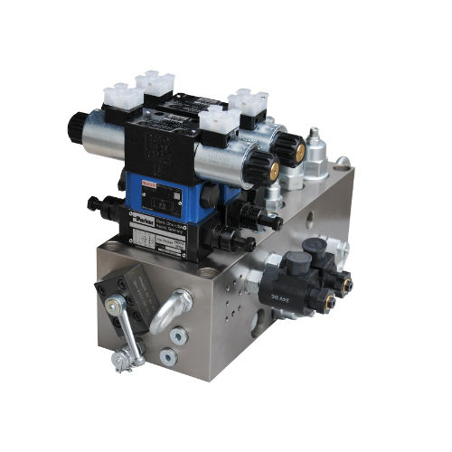
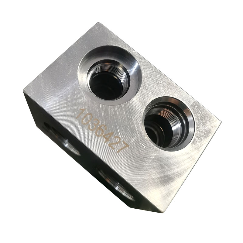
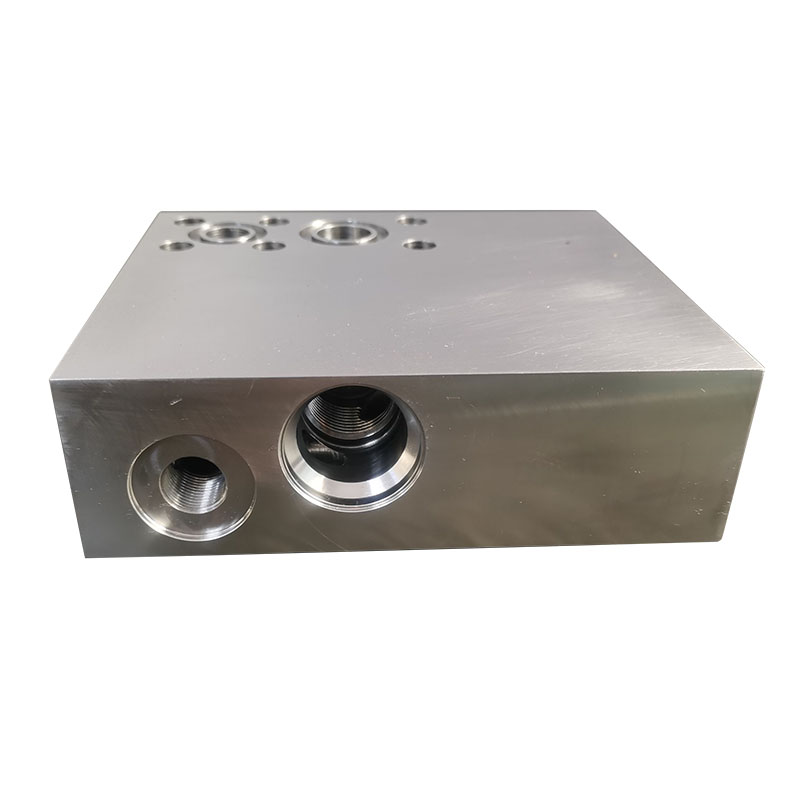
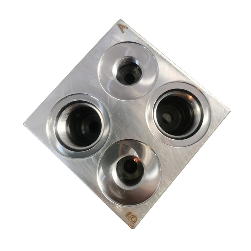
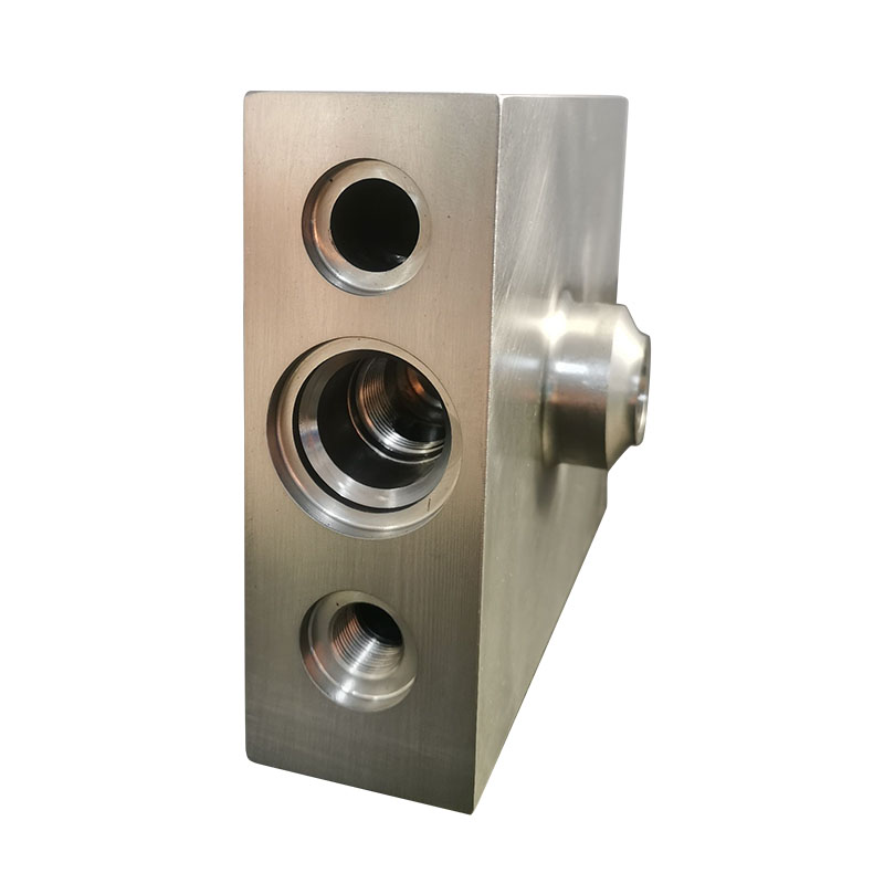
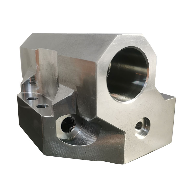
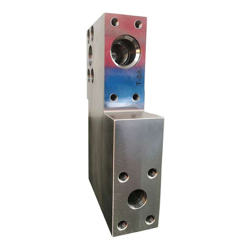
Non-Standard Hydraulic Valve Block
Non-standard customized hydraulic valve blocks Qingdao Micro Precision Machinery Co., Ltd. is a manufacturer specializing in the design and processing of non-standard hydraulic valve blocks. We have been focusing on the design and production of hydraulic valve blocks for more than 20 years. Our products have extremely high stability and their price advantage is also very obvious. Covering most of the European and American markets. We look forward to becoming your long-term partner in China.
Send Inquiry
Non-standard customized hydraulic valve blocks Qingdao Micro Precision Machinery Co., Ltd. is a manufacturer specializing in the design and processing of non-standard hydraulic valve blocks. We have been focusing on the design and production of hydraulic valve blocks for more than 20 years. Our products have extremely high stability and their price advantage is also very obvious. Covering most of the European and American markets.
We look forward to becoming your long-term partner in China.
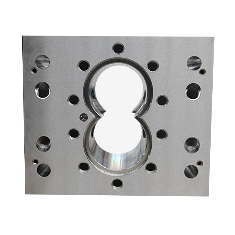
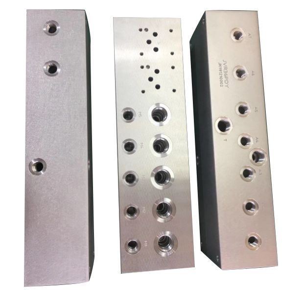
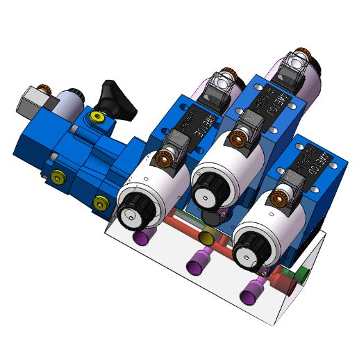
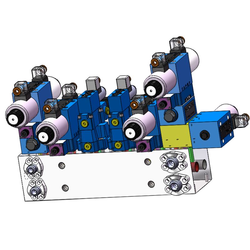
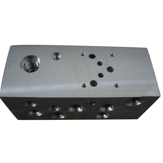
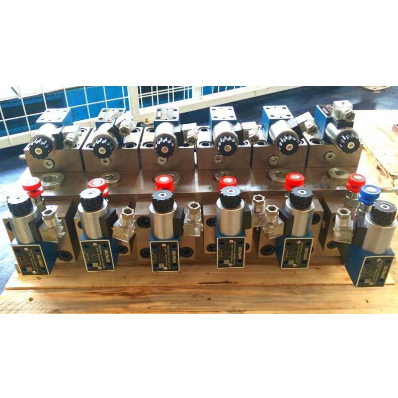

Non-standard hydraulic valve block materials are selected from No. 20 steel, No. 45 steel, forged, Q355D, cast iron and aluminum, etc. Accept materials specified by customers and provide customers with third-party material testing reports and flaw detection reports.
GET A QUOTATION NOW
Non-standard hydraulic valve quick layout:
When laying out non-standard hydraulic valves, you should consider whether the installation direction of the valve body is reasonable. The valve core should be in a horizontal direction to prevent the self-weight of the valve core from affecting the sensitivity of the valve. In particular, the reversing valve must be arranged horizontally. The shape, location and size of the public oil holes of the non-standard hydraulic valve block should be determined according to the design requirements of the system. When determining the installation parameters of each component on the non-standard hydraulic valve block, we should try our best to make the holes that need to be connected as orthogonal as possible, so that they are directly connected and reduce unnecessary process holes. Since each component has more than two oil holes, and these holes must be connected with the holes of other components and the public oil holes on the non-standard hydraulic valve block, sometimes direct connection is not possible, so design must be Necessary process holes. The hole design of the non-standard hydraulic valve block is to determine the number of process holes that need to be added when the holes are connected, the type and location size of the process holes, and the hole diameter and hole depth of the holes on the non-standard hydraulic valve block. Small wall thicknesses between closed channels must be checked for strength. It should be noted that the fixing screw holes of the hydraulic components on the non-standard hydraulic valve block do not collide with the oil passages, and their small wall thickness should also be checked for strength, etc.
The dimensions of hydraulic components installed on non-standard hydraulic valve blocks must not interfere with each other. The geometric dimensions of the valve block mainly consider the external dimensions of each component installed on the valve block, so that there is sufficient assembly space between the components. The distance between hydraulic components should be greater than 5mm. The electromagnet on the reversing valve, the pilot valve on the pressure valve and the pressure gauge can be appropriately extended beyond the installation plane of the adjustment block, which can reduce the size of the valve block. But be careful not to let the overhanging parts collide with other parts.
Things to note when designing non-standard hydraulic valve blocks:
1. In the design of non-standard hydraulic valve blocks, the oil circuit should be as simple as possible, and deep holes, inclined holes and process holes should be minimized. The hole diameter in the valve block must match the flow rate. Particular attention should be paid to the interconnected holes to ensure sufficient flow area. Pay attention to the direction and position of the oil inlet and outlet. It should match the overall layout of the system and the pipe connection form, and consider Regarding the craftsmanship of the installation operation, components with vertical or horizontal installation requirements must be ensured to meet the requirements after installation.
2. For components that need to be adjusted during work, the convenience of operation and observation must be considered when designing. Adjustable components such as overflow valves and speed control valves should be set at a position where the adjustment handle is easy to operate.
3. Components and key components that require frequent maintenance, such as proportional valves and servo valves, should be located above or outside the valve block to facilitate disassembly and assembly. In addition, a sufficient number of pressure measuring points should be set up in the design of the valve block for valve block debugging. For valve blocks weighing more than 30kg, lifting screw holes should be provided. However, on the premise of meeting the use requirements, the volume of the valve block must be Keep it as small as possible.


